Copper is a great conductor of electricity, with a low impedance and a high melting point, but you should still do your best to keep temperatures low. This is where you’ll need to properly size power rail widths to keep the temperature within a certain limit. A recommended methodology for working out the minimum track width is laid out in IPC-2221, It takes into account the current flowing in a given trace, as well as where the trace is in the stack up. a number of IPC-2221 calculators can be found online, however, it is sometimes easier to have a table of known values to look up.
PCB Power trace width vs Current
The PCB power trace width vs. current table below shows a number of trace widths and corresponding current values (this methodology comes from IPC 2221) that will aim to limit your temperature rise to 10 °C. This should give you an idea of how to size traces in your PCB:
| Current (A) | External 1 Oz CU trace width (mm) | Internal 1 Oz CU trace width (mm) | External 2 Oz CU trace width (mm) | Internal 2 Oz CU trace width (mm) |
|---|---|---|---|---|
| 1 | 0.300 | 0.781 | 0.150 | 0.391 |
| 2 | 0.781 | 2.03 | 0.391 | 1.02 |
| 3 | 1.37 | 3.56 | 0.684 | 1.78 |
| 4 | 2.03 | 5.29 | 1.02 | 2.64 |
| 5 | 2.77 | 7.19 | 1.38 | 3.60 |
| 6 | 3.56 | 9.25 | 1.78 | 4.63 |
| 7 | 4.40 | 11.4 | 2.20 | 5.72 |
| 8 | 5.29 | 13.8 | 2.64 | 6.88 |
| 9 | 6.22 | 16.2 | 3.11 | 8.09 |
| 10 | 7.19 | 18.7 | 3.60 | 9.36 |
| 15 | 12.6 | 32.7 | 6.29 | 16.4 |
| 20 | 18.7 | 48.7 | 9.36 | 24.3 |
| 25 | 25.5 | 66.2 | 12.7 | 33.1 |
| 30 | 32.7 | 85.2 | 16.4 | 42.6 |
I have a set of IPC-2221 derived netclasses in my default KiCad project, I will be be writing about that and PCB track clearance (both inter track distance, and Creepage and Clearance) shortly.
Limitations of the IPC-2221 and IPC-2152
IPC-2221 is considered to be very pessimistic about the temperature rise that it is trying to report, it doesn’t take into consideration different substrates or other tracks nearby. Meaning that the minimum width value that you calculate from IPC-2221 is probably an overestimate.
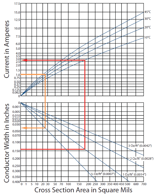
The chart to the right comes from IPC-2221, Appendix B. The data in this chart compares measured temperature rise values for a given current supplied to traces of the same size. We can see that the IPC results greatly overestimate the expected temperature rise for all current values. This is why the calculators based on IPC-2221 may tend to overestimate the required conductor width.
Mike Jouppi and others (IPC 1-10b task group) did a lot of work for the IPC-2152 standard and attempted to expand the available set of data to include multiple nomographs for determining trace width, temperature rise, substrates and current limits. They attempted to correlate different design conditions found in circuit boards, including variations in copper weight, presence of planes, trace-to-plane distance, and usage in air vs. vacuum.
Better than IPC-2221 or IPC-2152?
If you are making a product, and want to reduce the physical size of your PCB, it might be worth doing your own investigation into the thermal management of your own device, for example, you may find that your maximum current flow is only present for a short period of time, and you can under-size your tracks due to it being a transient, with a lower steady state condition.

